The membrane test – experimental considerations
June 7, 2021
High temperature aging in non-aggressive fluids
September 19, 2022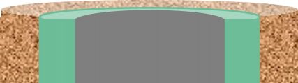
With the increased interest in underground storage of carbon dioxide and high temperature geothermal wells, along with the development of new materials for zonal isolation, there is a need to evaluate the long-term durability of zonal isolation materials under different downhole conditions. The key exposure parameters are temperature, pressure, local chemical environment (fluid, rock) and time.
There are many possible exposure conditions which, when combined with a multitude of new materials means that standardised test procedures have not been developed. However, much can be learned from what has been done before.
This is the first in a series of articles that will discuss key factors to be considered when testing and evaluating durability of materials for zonal isolation applications.
- Introduction: comparison of the sample and the well geometry and fluid exposure conditions
- High temperature aging in the presence of non-aggressive fluids
- Aging in the presence of aggressive fluids
- Extrapolation of laboratory results to the well environment
- Summary of some key references
Introduction
The chemical durability of set Portland cement systems exposed to fluids under simulated downhole conditions has been extensively studied. Many researchers have studied the durability of set cement systems in contact with CO2 laden fluids, for long-term underground storage. The required lifetime of sealants for CO2 storage wells are often stated as thousands of years. For geothermal wells the required lifetime will be tens of years.
The chemical durability of Portland cement systems and other materials is typically investigated by placing set samples in contact with the required chemical system at the appropriate temperature and pressure for various times. The samples are then examined to evaluate changes in their chemical structure and properties as a function of exposure time.
Samples, generally cylindrical and with a length to diameter ratio of 2, are usually placed directly in contact with the test fluid so that chemical interactions occur on the curved surface and the flat ends.
Although the process sounds relatively straightforward, the experiments may be complicated requiring sophisticated equipment and detailed processes to ensure that the tests can be performed in a safe manner.
A key challenge is to extrapolate behaviour seen in these tests to the situation in a well.
Laboratory sample geometry
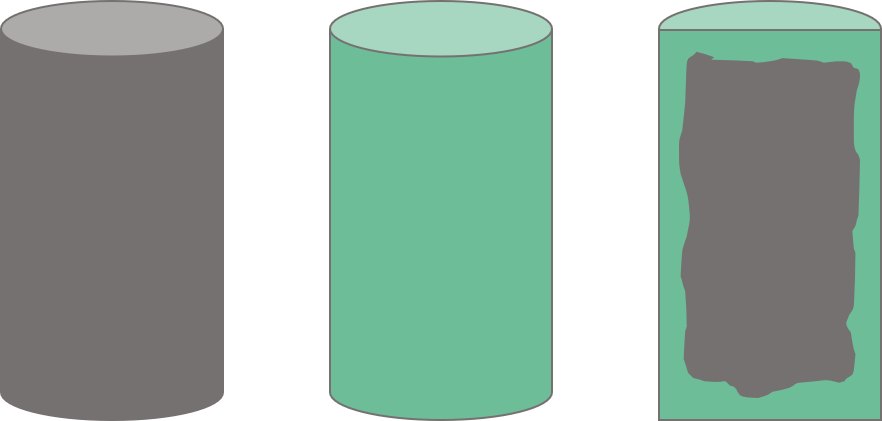
The figure below shows the situation with cylindrical samples placed in direct contact with the test fluid. The chemical interactions occur over all the surfaces; throughout this article the chemically altered cement will be shown as green and the unaltered cement grey. If the cylindrical sample is cut in half lengthways, as shown on the right, there is a roughly cylindrical volume of unaltered cement in the middle. The thickness of the altered zone will be similar from the ends and from the curved surfaces.
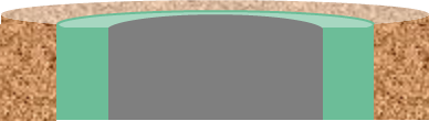
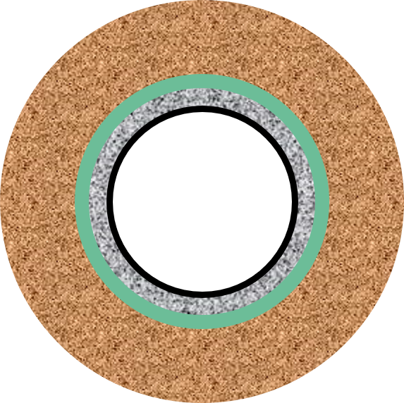
There are some exceptions to the complete exposure of samples to the fluid. Duguid cast cement samples inside permeable rock samples and then clamped seals on the flat faces so that fluid-cement interactions only occurred on the curved cement surfaces and via diffusion of the fluid through the permeable rock sample. In this case the sample was disc shaped as the length of the cement cylinder was roughly 1/3 of its diameter. The distribution of the rock, chemically altered cement, and unaltered cement are shown in cross section below.
Laudet et al. covered the curved surfaces of cylindrical cement samples with Polyetheretherketone (PEEK). The idea was to create a one-dimensional attack of cement by CO2 saturated fluids. The PEEK was partially successful at limiting attack through the curved surfaces.
Lende et al. in a recent paper discussed the use of hassler cells to force fluids through cement samples. An elevated differential pressure was used to accelerate the fluid penetration rate. The chemical attack did occur from one end but the required reaction times were still long. The number of samples that could be tested simultaneously was also limited by the more complex equipment.
The size of laboratory samples, often 2.5 cm diameter and 5 cm long, is comparable with the width of the cement sheath in wells. However, the geometry of the attacked surface is generally different, from that in well situations.
Well cement geometry
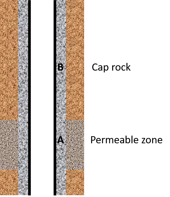
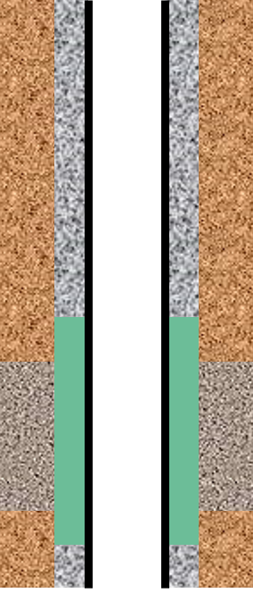
Consider the well situation below with cement in front of a permeable zone (A) and higher up the well between the casing and an impermeable formation (cap rock – B).
Cement in front of a permeable formation – situation A
In this case chemical alteration of the cement will occur from the outer surface as shown below (well cross-section). This is like the geometry of Duguid except that in the well case the inner surface of the cement is in contact with casing.
Cement in front of impermeable rock – situation B
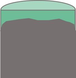
In case B if the fluid ever contacts the cement, the contact is likely to be across the entire annular area as the axial length travelled will be far greater than the annular width. This discussion assumes that no micro-annuli or mud channels present are present.

Fluid flow conditions
In the well situations discussed above the fluid in contact with the cement is in a static condition. Chemical attack is driven by diffusion of ions from high concentration regions to low concentration regions. The cement is not in contact with flowing fluid and the ratio of “fresh fluid” to cement volume is low.
This is one area where laboratory tests can be more aggressive than actual well situations. In laboratory tests volumes of fresh fluid to cement volume are often high. In many cases the fluid is also replaced at regular intervals. Consequently, the rate of attack in laboratory situations may be significantly higher than in actual well situations. This can lead to underestimates of the lifetime of well sealants. Accelerated aging can be exacerbated by convection in the fluid or stirring of the fluid in contact with the cement. In both cases dissolved ions are transported away from the cement surface leading to an increased rate of attack.
Injection or production zones
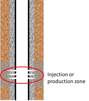
The well situations where cement will be in contact with flowing fluid are during injection and production. Exposure to flowing fluid may be for relatively short times, e.g. during acid stimulation treatments or over much longer periods of times (tens of years -ref. SRCCS Report P67) for injection of CO2 for storage or injection/production of water for geothermal applications. In these cases, laboratory experiments with fluid flowing around the samples, which is frequently replaced, will be appropriate.
However, the flowing fluid will only be in contact with cement close to the perforations, as indicated by the red ring in the diagram above. Degradation of cement in this area may be important for mechanical stability of the well/formation but isolation of the production/injection zone will be provided by cement in the annulus well away from the flowing fluid.
Finally, once the well is plugged the cement will only be in contact with static fluid.