Micro-annulus – importance for hydraulic isolation
April 10, 2021Long-term durability of materials for zonal isolation
November 14, 2021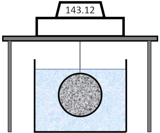
Introduction
The procedure to measure the bulk volume changes of well cements under impermeable conditions (The membrane test) is described in API RP10B-5, first edition April 2005 and the identical document ISO10426-5:2003. A diagram showing a rough outline of the experiment (placement of the membrane in water and suspended from a balance) are shown in the figure above.
There are two experimental details that can have a significant effect on the results if they are not followed.
Firstly, the procedure clearly states that the slurry must not show any free fluid and must not have any entrapped air. If the slurry does not meet these requirements, then the bulk volume changes measured are likely to be overestimated as explained below. The effect of sedimentation and free fluid on the measurement of compressive strength has already been discussed but the effect on bulk shrinkage measurements can be even more significant and less obvious to identify.
Secondly, the choice of the membrane is a critical component of the test. The API/ISO procedure states that the membrane must be flexible and impermeable but there is no indication of the type of membrane to use.
These two key points will be discussed in the sections below.
Slurry design and stability
This section will first describe the behaviour of an ideal cement slurry without free fluid in the membrane test followed by a discussion of the effect of free fluid generation or the incorporation of air.
Slurry without free fluid
As discussed in a previous article, once the cement starts to hydrate the bulk volume change follows the chemical shrinkage (referred to as inner hydration shrinkage in API RP 10B-5) until a rigid structure develops within the cement. From this point onwards (A in the figure below) the bulk volume changes deviate significantly from the chemical shrinkage as hydration progresses.
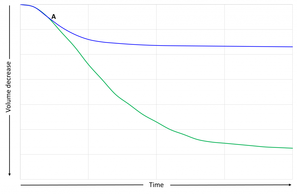
The chemical shrinkage shown in the figure above is measured in a separate test or calculated as a function of the degree of hydration, as discussed in a separate article.
Slurry with free fluid
Now what happens if the cement slurry shows free fluid during the induction period?
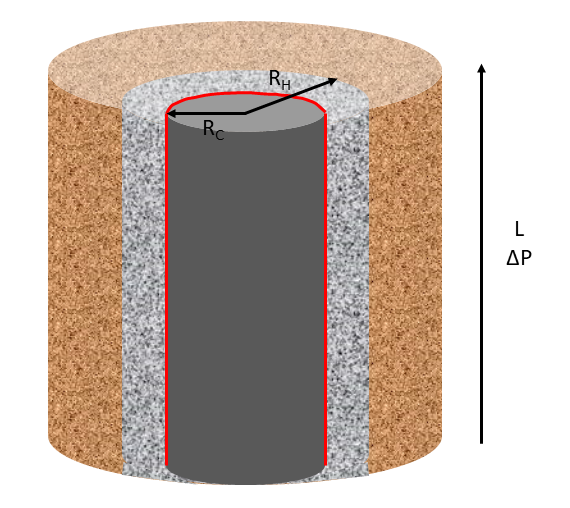
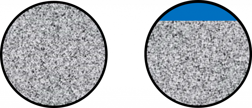
The idealised figure below shows a cement slurry placed inside a membrane (thick black line). On the left is the slurry immediately after filling the membrane and on the right is the situation for a slurry showing free fluid sometime after the start of the experiment but before there is any significant hydration of the cement: the free fluid (exaggerated) is shown in blue.
Referring to the figure below. Initially the shrinkage measured will follow the same trend as in the previous case up until point A, where a rigid structure starts to develop in the cement. In the previous case the measured bulk shrinkage deviated from the chemical shrinkage at this point. However, when free fluid is present the behaviour is different. As hydration continues water in the pore spaces is consumed as before, but in this case the free fluid at the top of the cement enters the set cement via capillary suction. This will lead to a reduction of the volume of the membrane until all the free fluid is consumed (red line in the figure below).
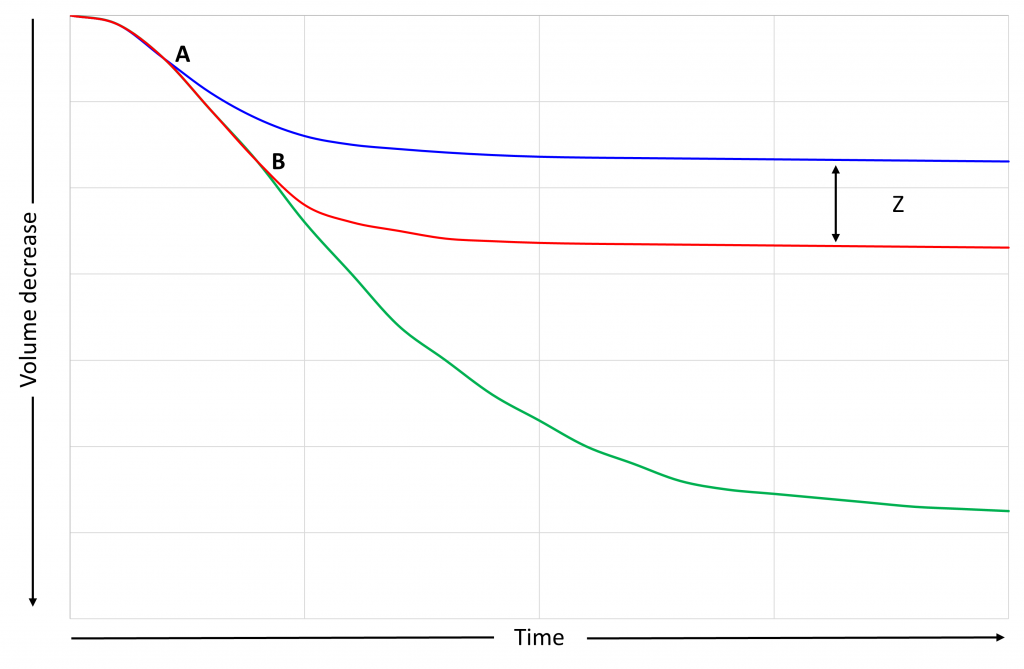
The bulk shrinkage indicated by the red line is a consequence of the presence of free fluid. The difference between the volume decrease indicated by the red and blue lines (Z) will be close to the volume of free fluid present in the test.
Note that the point A will occur at a smaller volume decrease in the slurry with free fluid as the effective water-to-cement ratio in the slurry will be lower and the rigid structure will develop at a slightly lower degree of hydration.
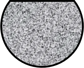
The final shape of the set cement in the membrane will be something like that shown below (again exaggerated).
Note that the volume of free fluid may occur in the membrane test, is not necessarily the same as that measured in the standardised free fluid test as the geometry is different and the time that the slurry remains static will not be 2 hours.
Presence of air
The behaviour if some air is trapped on the top of the slurry during filling or if air trapped in the slurry migrates to, and breaks out from, the surface of the slurry will be similar to that with free fluid: the measured bulk expansion will be higher than expected due to re-adsorption of the air at the top of the sample.
Membrane
As mentioned above, the choice of the membrane is important. Frequently condoms are used; these are made from either latex, polyurethane, or polyisoprene. Although these materials are flexible, they are not impermeable over the long-term allowing water to penetrate (Lura, P., Jensen, O.M. Measuring techniques for autogenous strain of cement paste. Mater Struct 40, 431–440 (2007)), significantly affecting the measurement.
The API/ISO procedure recommends coating the membrane inside and out with silicone grease to reduce the permeability, but this will be susceptible to operator differences.
An alternative method has been suggested by Lura and Jensen. They used polyurethane condoms with paraffin oil as the buoyancy liquid. Latex or polyisoprene membranes cannot be used with paraffin oil. The density of the paraffin oil, at the temperature of the test, must be used to convert the mass change measured to the volume change.
Note: Lura and Jensen performed these tests at 20°C in a controlled laboratory environment. The safety aspects of using paraffin, or other, oil for these tests has not been evaluated.
If the membrane does allow water to enter it may not be always obvious during the measurement. To confirm that the membrane has remained impermeable the mass of the set cement and membrane in air can be measured at the end of the test. The buoyancy fluid will need to be removed from the outside of the membrane before weighing.